System Functions
Look at the main interface of CluBlocks Pro, it includes four parts, that is, Blocks selection, text code (MicroPython language) (hidden), system function and message prompt area. Shown below.
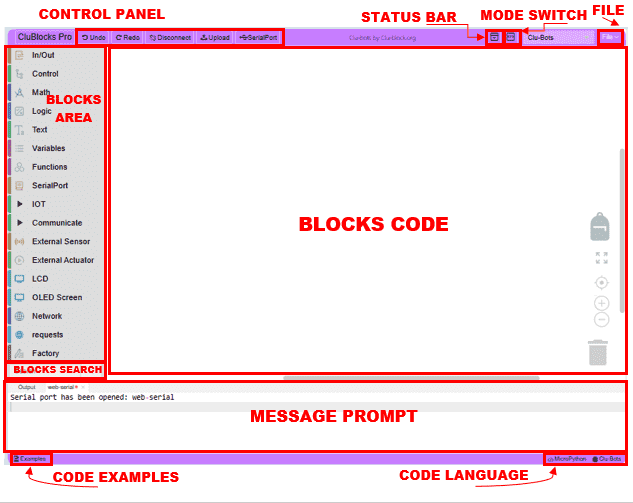
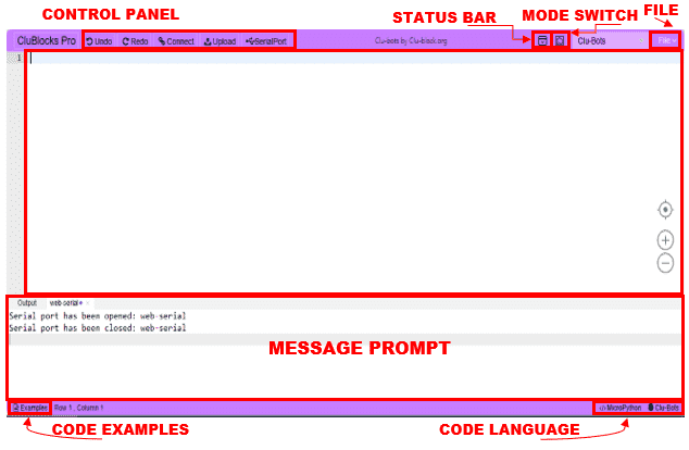
The CluBlocks Pro interface is divided into several key sections:
- Message Prompt: Provides useful information during program development. If there are errors, messages will be displayed here to help you identify and correct them. And Serial Port information.
- Blocks area: Contains the available categories and blocks.
- BLOCKS CODE: It is the workspace where blocks are dragged and connected to create the program.
- TEXT CODE: Shows the MicroPython code generated from the blocks, in addition to being able to write MicroPython code. warning: If codding on the MicroPython the code will disappear if moving to the block coding mode
- CONTROL PANEL: Includes the main buttons to interact with the interface
- Code examples: Se encuentran los códigos de los proyectos por nivel.
| The undo function is that after mistakenly deleting the code when writing the code, we can click the left arrow or press + directly to restore the accidentally deleted code Ctrl+Z | |
| Redo, on the other hand, is the opposite of +, which is to resume the previous action, which can also be accomplished by clicking the right arrow | |
| Before performing an upload, you must select the serial port where your microprocessor (ESP32) is connected. Simply select it and press the connect button. | |
|
When the user has finished writing their program and wants to test if the block code logic is correct, it will be compiled and uploaded to the ESP32. The success rate will be displayed in the message area. If “Upload failed” appears, you should check your code and physical connections according to the instructions. The messages area is usually a place to give informative feedback to students. During the compilation and upload process, please indicate whether the compilation or upload was successful. If it didn’t work, please explain the reason for the failure. |
|
| It is used to display data received by the serial port in real time, as well as to interact with the ESP32. | |
| Click it to show or hide the status bar (Message Prompt) | |
| Click it to switch between block programming and IDE (code text). When switching from blocks to text, you will see the code generated by the blocks. “Caution: changes made in code will not be reflected in the blocks area, and all work will be lost if you do not save it in advance. Also, the pin numbering changes to that of the ESP32 GPIOs.” | |
 |
|
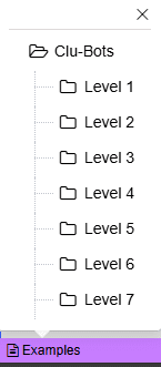 |
Code for all projects and micro-projects separated by level; we hope you will use them “only in extreme cases” to verify or back up when there seems to be no solution. |
| You can drag and drop the code you want to use into a different project than the one you’re currently using. | |
| Expands the view to include all blocks in the programming area (full zoom out) | |
| Clicking on this symbol places us at the beginning of the code in the block code area | |
|
Zoom helps us adjust the size, increase or decrease the size of the blocks in the block area and the blocks code area (zone) -Of course, you can also use the mouse wheel directly to zoom.- |
|
 |
Bin: To delete a selected element, it is dragged over it. |
Browsing and Using Blocks
1. Explore Block Categories: In the “Blocks Area” (on the left), you’ll find categories like “InOut”, “Control”, “Math”, “Logic”,, “Variables” “Functions”, “SerialPort” , “IOT” , “Communicate” , “External Sensor”, “External Actuador”, “LCD” , “OLED Screen” , “Network” , “requests”, and “Factory”. Click on a category to see the blocks available within it.
2. Drag and Drop Blocks: Click on a block within a category and drag it to the “Blocks Code Area” (the middle area).
3. Connect Blocks: Blocks have connectors that allow you to link them together to create a sequence of instructions. Drag the output of one block to the input of another to connect them.
4. Adjust Blocks: Some blocks have configurable options. Click on the block to access these options.
5. View Code in Text: The “Code in Text Area” displays the MicroPython code corresponding to the blocks you have connected. This helps you understand the relationship between visual programming and real code.
6. Use the Control Tools:
Zoom Buttons: The “+” and “-” buttons at the bottom of the “Code in Blocks Area” allow you to zoom in and out of the view of the code in blocks.
The button with the circle and crossed lines centers the view.
Trash: The trash can icon in the “Code in Blocks Area” is used to delete blocks. Drag the blocks you want to delete to the trash can.
Basic example:
To create a program that prints “Clu-Bot” in the status bar:
- Find the “Serial Port” category.
- Drag the text block to the “Code Blocks Area“.
- Type “Clu-Bot” inside the text block.
- In the Control Panel toolbar, click “Connect” and select your device.
- Click “Upload“

You will see “Clu-Bot” in the “Message Prompt“